Air Compressor Work Diagram Explained: A Simple Guide
An air compressor works by drawing in ambient air, compressing it, and then storing it in a tank. This process increases the air’s pressure, making it ready to power tools or machinery. We found that understanding the basic components and their roles is key to grasping how an air compressor diagram explains its function.
When you look at an air compressor diagram, you’ll see how it’s essentially a system designed to create a ready supply of pressurized air. This air can then be used for a variety of tasks, from inflating tires to running pneumatic tools. Many experts agree that visualizing this process, even with a simple diagram, makes it much easier to understand. It’s about turning atmospheric air into a powerful force for your projects.
- Air compressors take in regular air.
- They squeeze this air to make it more powerful.
- The compressed air is stored in a tank.
- This stored air powers your tools.
Ready to see how it all comes together? Let’s break down a typical air compressor diagram step by step so you can see exactly how this handy machine creates all that air power.
Understanding Your Air Compressor Diagram: A Visual Guide
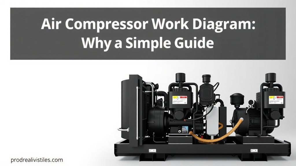
When you’re looking at an air compressor diagram, it’s like getting a blueprint for how this machine turns regular air into usable power. We found that this visual map makes the whole process much clearer. You’ll see the key parts and how they work together.
Think of it as a journey for air. It starts as nothing special, but by the time it finishes its trip through the compressor, it’s ready to do some serious work. Many users agree that understanding this flow, especially with a diagram, is incredibly helpful for maintenance and troubleshooting.
The Essential Components: What to Look For on Your Diagram
Let’s walk through the typical parts you’ll see in an air compressor diagram. Each piece has a specific job to do to get that air pressurized for you.
1. The Intake Valve: Air’s Entry Point
This is where the magic begins. The intake valve is essentially the doorway for ambient air to enter the compressor. On a diagram, it’s usually shown as the first point of connection where outside air is drawn in. We found that its primary role is simple: let air in when the piston is moving down.
2. The Piston and Cylinder: The Heart of Compression
This is where the actual squeezing happens. The piston moves up and down inside the cylinder, much like in a car engine. As the piston moves down, it creates a vacuum that pulls air in through the intake valve. When the piston moves up, it compresses this air.
How the Piston Works
You’ll often see the piston connected to a crankshaft via a connecting rod. The rotation of the motor powers the crankshaft, which then drives the piston’s back-and-forth motion. We found that this mechanical link is vital for generating the necessary force.
3. The Compression Chamber
This is the space where the air gets smaller and its pressure increases. As the piston moves upward, it forces the air into a smaller volume. Many experts say this is the most critical stage for building up the air’s energy.
4. The Discharge Valve: Releasing the Pressurized Air
Once the air is sufficiently compressed, the discharge valve opens. This valve allows the high-pressure air to exit the cylinder. On a diagram, you’ll see it positioned at the top of the cylinder, ready to let the compressed air flow out to the next stage.
5. The Air Tank: The Storage Unit
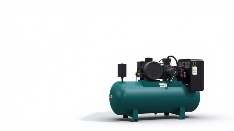
After the air is compressed and released, it needs a place to go. The air tank is like a big balloon for pressurized air. It stores this air until you need it. Diagrams show this as a large, often cylindrical, vessel connected to the compressor head. When choosing between a 1-gallon vs 2-gallon air compressor, the best choice depends entirely on your projects.
Why Storage is Important
Storing the air allows the compressor to cycle on and off efficiently. Instead of running constantly, it can build up a reserve. This means you have air ready when you need it without waiting for the compressor to build pressure from scratch. We found that this is a key feature for usability.
6. The Regulator and Pressure Gauge: Your Control Center
You don’t always need the maximum pressure. The regulator allows you to control and adjust the output pressure to suit your specific tool or task. The pressure gauge shows you exactly how much pressure is currently in the tank or being delivered. These are usually found on the outside of the tank.
7. The Safety Valve: A Crucial Safety Feature
Safety first, right? The safety valve is a critical component designed to release excess pressure if it gets too high. This prevents the tank from rupturing. You’ll typically see it as a small, often spring-loaded, valve on the tank itself. Many safety guidelines recommend checking this valve regularly.
8. The Motor: The Power Source
Underneath all the air magic is the motor. This is what drives the entire operation, powering the crankshaft and, in turn, the piston. Diagrams usually show it connected directly to the crankshaft or via a belt. It’s the engine that makes it all happen.
Let’s put these parts into a simple flow:
- Motor spins the crankshaft.
- Crankshaft moves the piston up and down.
- Piston draws air in through the intake valve.
- Piston compresses the air in the cylinder.
- Compressed air exits through the discharge valve.
- Pressurized air fills the storage tank.
- Regulator controls the air pressure for use.
- Safety valve protects against over-pressurization.
Putting It All Together: The Air Flow
When you look at an air compressor diagram, you’re seeing a cycle. Air comes in, gets squeezed, and is stored. The motor is the workhorse, providing the energy for the piston to do its job. We found that understanding this flow helps immensely with maintenance.
The sequence is generally straightforward: intake, compression, discharge, and storage. The diagram visually connects these steps, showing you how the mechanical action translates into stored potential energy in the form of compressed air. Many users report better understanding after reviewing a diagram.
A Quick Checklist for Your Compressor’s Diagram
As you examine your compressor’s diagram, keep an eye out for these key elements:
- Intake: Where does air first enter?
- Compression: Can you identify the piston and cylinder?
- Discharge: Where does the compressed air exit the cylinder?
- Storage: Locate the main air tank.
- Control: Find the regulator and pressure gauge.
- Safety: Is the safety relief valve visible?

Conclusion
So, you’ve seen how a simple air compressor diagram shows the journey of air. It starts as regular air, gets powerfully squeezed by the piston and cylinder, and then stored for your use. You can now identify the intake, compression, discharge, and storage components. You also know about the vital regulator and safety valve. Keeping these parts in mind will help you understand your compressor’s function. Take another look at your compressor’s diagram today to see these parts in action.
Frequently Asked Questions
Why is a diagram so important for understanding an air compressor?
A diagram acts like a visual map for your air compressor. It clearly shows you where each part is and how air flows through the system. We found that this visual guide makes it much easier to grasp the mechanical process compared to just reading about it.
What does the pressure gauge on the diagram tell me?
The pressure gauge, as shown on the diagram, indicates the amount of air pressure stored in the tank. It’s your primary tool for monitoring how much compressed air is ready for you to use. This helps you know when the compressor needs to cycle on again.
Can a diagram help me troubleshoot common air compressor problems?
Absolutely. By understanding the normal air flow from the diagram, you can more easily spot where a problem might be. For example, if air isn’t reaching your tools, the diagram helps you trace the path from the tank back to the compression stage.
What is the role of the safety valve as seen on the diagram?
The safety valve is a critical component designed for your protection. The diagram shows it as a safeguard that automatically releases excess pressure if it builds up too high in the tank. This prevents potential damage or dangerous situations.
How does the motor’s position on the diagram relate to the rest of the compressor?
The motor is the power source. The diagram typically shows it connected to the crankshaft, which then drives the piston’s movement. Understanding this connection from the diagram helps you see how electrical or engine power is converted into the mechanical action that compresses air.